Thu May 07 2026
Built a circuit with two independent GPIO loops connected by code only. Learned about explicit vs implicit power sources and resistor placement patterns.
Written by: Cesar
3 min read
My next Raspberry Pi Pico project looks simple on the surface, but it taught me a lot about how GPIO pins actually work.
The project has two separate loops that seem connected but aren’t — they’re connected by code only.
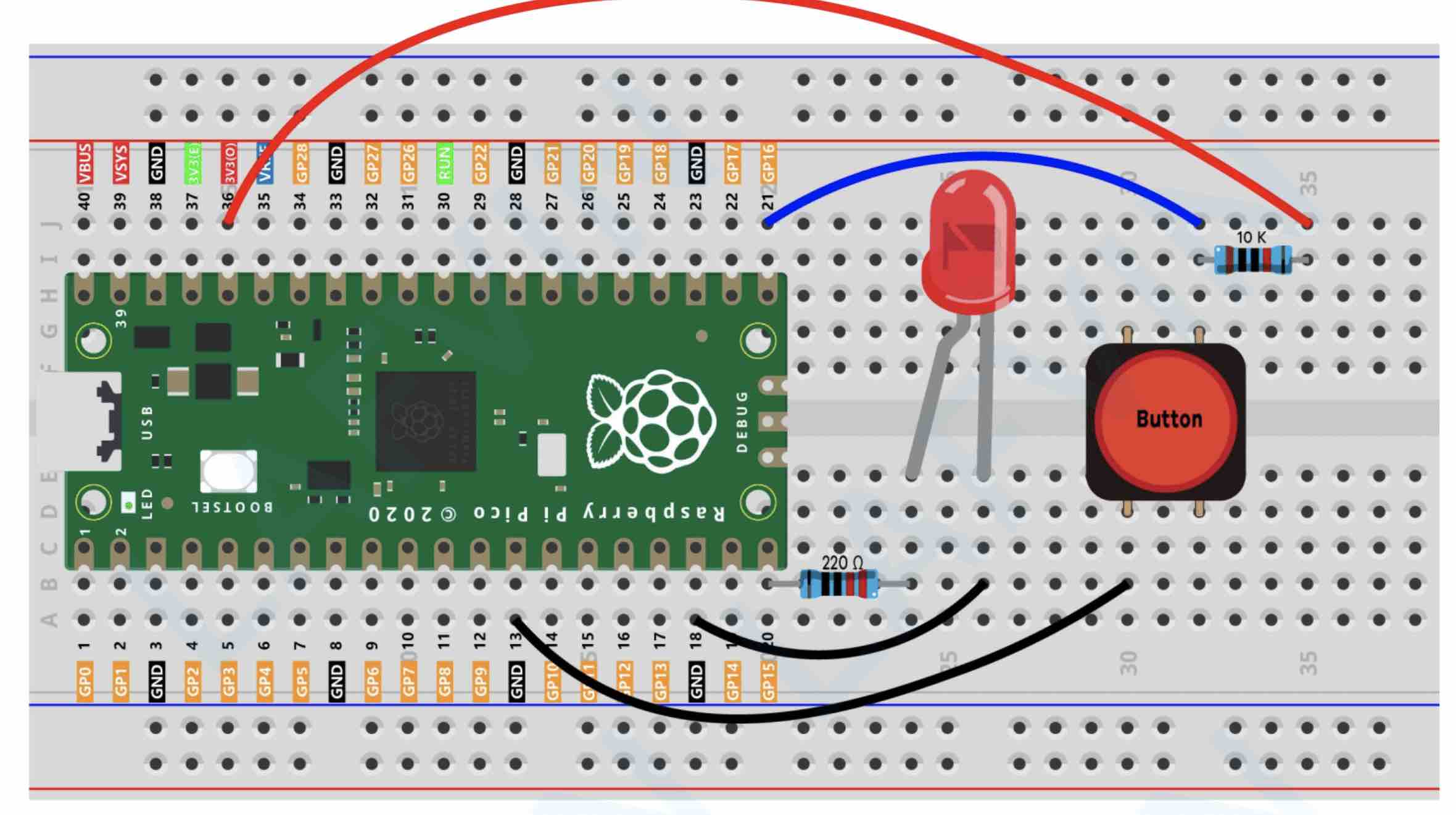
Loop 1 (GPIO16): Listens for input from a push button Loop 2 (GPIO15): Outputs power to an LED
This is where things got interesting.
GPIO16 (input loop): The pin is set to INPUT. If a pin is INPUT, you need to wire something to create a baseline since we are reading from that GPIO16. It can be the 3.3V we have or it can be GND — it depends on whether we use the internal pull-up/pull-down resistors for pins in code. Without a baseline connection, the pin has no defined state to read.
GPIO15 (output loop): The pin is set to OUTPUT. Because it’s an output pin, it implicitly has access to the 3V3 power source. No need to wire it explicitly — the Pico handles it internally.
That was a revelation. Output pins are powered. Input pins need external power if you’re pulling them high.
The project also showed me two distinct patterns for resistor placement:
Pattern 1: Pin → Component When GPIO15 (output) connects to the LED, there’s a current-limiting resistor between the pin and the LED. This protects the LED from overcurrent. The resistor goes between the pin and the component.
Pattern 2: Power → Pin (Pull-Up or Pull-Down) When GPIO16 (input) connects to create a baseline voltage, you can use two approaches:
Pull-up: Wire 3.3V → resistor → GPIO16. Pin reads HIGH by default, goes LOW when button grounds it.
Pull-down: Wire 3.3V → button → GPIO16, then GPIO16 → resistor → GND. Pin reads LOW by default, goes HIGH when button connects to 3.3V.
Here’s the control logic:
import machine
import time

button = machine.Pin(16, machine.Pin.IN)
led_onboard = machine.Pin(15, machine.Pin.OUT)

while True:
    if button.value() == 0:
        led_onboard.value(0)
    else:
        led_onboard.value(1)
The behavior depends on your resistor approach:
With pull-up: The LED is ON by default (HIGH) because the button pin reads HIGH. When you press the button, it grounds the pin (reads 0), and the LED turns OFF.
With pull-down: The LED is OFF by default (LOW) because the button pin reads LOW. When you press the button, it connects to 3.3V (reads 1), and the LED turns ON.
Same code, opposite behavior. The resistor configuration changes the logic.
This is the foundation for building more complex circuits. Small project, big lessons.
Next: More complex multi-pin projects with these fundamentals locked in.